• Welcome to For E Bodies Only !

    We are a community of Plymouth Cuda and Dodge Challenger owners. Join now! Its Free!

Question on difference between 518 R46r and 46re

mistreta

Well-Known Member
Joined
Sep 19, 2018
Messages
70
Reaction score
8
My 72 cuda has a 518 trans with OD. I'm trying to find the correct neutral safety switch. The trans is shifted when overdrive is needed with a switch under the dash. Not electronic.
I think I have the 46R trans so I think the 3 prong switch is what I need. What is the best way to see what 518 trans I have, or see if possible the switch on the trans?

Thanks Tony in Mi
 

Mopars & Missiles

Well-Known Member
Joined
Jan 1, 2012
Messages
234
Reaction score
103
Not familiar with a 46r. I've only known the 46rH and the 46rE. The H is hydraulically controlled, the E is Electronically controlled.
 

basketcase70

Member
Joined
May 26, 2022
Messages
16
Reaction score
4
Location
Chiloquin, Or
46RH and 46RE is just 1992 and up nomenclatures for the 518. The 4 refers to the number of forward gears. The H in RH refers to hydraulic actuation (spool valve gear selection). The E in RE refers to electric actuation (computer controlled solenoid gear section) of the primary gear box. The 2,6,7,8 etc. refers to the torque capacity. Overdrive (and lockup if included) is controlled by solenoid(s) in both.

Because, aside for the overdrive, the 46RH is virtually the same as a 727 (pre computer) and the only solenoids present control the overdrive function and lockup (when present), the use of a vacuum switch or mechanical throttle position switch and external hydraulic pressure switch(s) can be used to control the overdrive and lockup functions in place of the factory computer.

The neutral safety switch will interchange with previous three speed automatics. I used the the original one from my 727. Same goes for the speedometer drive, just pulled it out of the 727 and reused it. Shifter and throttle valve linkage (minor adjustment) were able to be reused also.

Because I used adjustable pressure switches to allow me set the speed overdrive and lockup engaged (verses using fixed switches that give you a predetermined and nonadjustable speed of overdrive and lockup engagement), I placed the box I built to contain the switch gear in the engine compartment. This required using a 3' long hydraulic line to the connect hydraulic switches to the #4 test port. It does literally make pulling over, popping the hood, and resetting them a 30 second evolution, taking the pain out of the initial setup and making it really easy to make minor adjustments when retuning the engine.
 

basketcase70

Member
Joined
May 26, 2022
Messages
16
Reaction score
4
Location
Chiloquin, Or
Three pin neutral safety switch came in around 1969 or so. A 1972 would use a 3 pin switch (center pin is for the neutral safety circuit, the two outside pins are the pass through for the backup light circuit when reverse is engaged).
A further note on the overdrive operation- The 46RH has a three pin plug for controlling the overdrive and lockup solenoids. the forward pin is the ground circuit for overdrive, the center pin is B+ (12 volts) supply circuit, and the rear pin is the lockup circuit
 

basketcase70

Member
Joined
May 26, 2022
Messages
16
Reaction score
4
Location
Chiloquin, Or
The hydraulic switches control the ground circuits. Rather than use a single toggle to cut the 12 volt supply, engaging or cutting both the overdrive and lockup circuits in unison, I used two toggle switches, one in each ground circuit for independent control, allowing overdrive without lockup.
 

mistreta

Well-Known Member
Joined
Sep 19, 2018
Messages
70
Reaction score
8
Wow, You really did your homework on transmissions. I will save this info, it is very helpful understanding my 518.
Thank you for your help

Tony
 

Katfish

Well-Known Member
Joined
May 14, 2022
Messages
314
Reaction score
162
Location
Palm Bay, FL
518 Control

Completely automatic, wanted my daughter to be able to drive it.

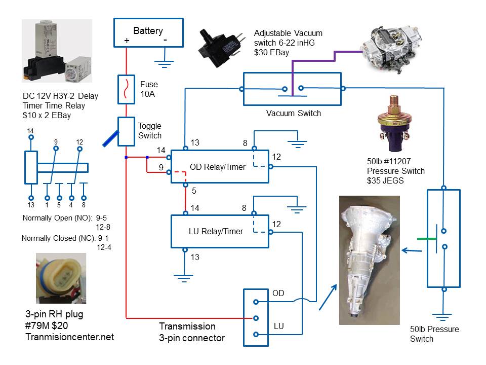
The control module automatically turns on/off the overdrive and lock-up for the transmission.

The 518 (46RH) is hydraulically controlled and uses 2 servos to enable the OD and LU.

The 3-pin connector on the transmission supplies the control voltages.

The center pin always has 12V power connected. The 2 outer pins are switched grounds. The front pin is the OD ground, the rear pin is the LU ground.

The module works according to the following sequence.

1) The 12V toggle switch supplies voltage to the relays and transmission center pin.

2) When the hydraulic pressure trips (50mph/adjustable) the pressure switch, ground is supplied to the vacuum switch. When speed is below 50mph, hydraulic switch opens, disabling OD.

3) When there is enough vacuum, the vacuum switch closes, providing the OD relay ground. Under heavy acceleration, vacuum drops, opens switch, OD is disabled.

4) When OD relay has ground and 12V, it waits 10sec, then supplies 12V to the LU relay and ground to the transmission OD pin, enabling OD.

5) Now the LU relay has 12V, it's already grounded. It waits the 10 sec programmable delay then provides ground to the transmission LU pin. So lock up doesn't occur until OD has been enabled and on for 10sec.

6) The programmable delays for both relays fix the situation when speed is fluctuating around 50mph. This would normally cause the OD to kick on/off, the 10 sec (programmable) delay stops this from happening.

 
Last edited:

basketcase70

Member
Joined
May 26, 2022
Messages
16
Reaction score
4
Location
Chiloquin, Or
Very detailed and concise diagram and explanation. I seriously considered using it or one very similar, but decided for my application to forgo the delay relays and run an adjustable pressure switch and toggle switch in each ground circuit to control overdrive and lockup engagement individually, as I detailed earlier in the thread.

After some experimentation, the hydraulic pressure switch controlling overdrive was set to engage at 35MPH. This allows using overdrive in the city on the major surface streets where the speed limit is 40MPH. I tried initially setting the switch for lockup to engage at 41MPH, but decided the resulting 1175RPM from engaging both the overdrive and lockup at that speed was just a little too low, especially after I leaned out the carburetor to try and improve the highway fuel economy beyond what the overdrive was providing. I have found I like having lockup engage about 47-48MPH with the current spark advance, carburetor setting, tire diameter, and 3.54 gearing. With both toggle switches on, the speeds chosen do not result in any rapid on/off cycling events and the resulting operation is completely automatic and hands off.
 

basketcase70

Member
Joined
May 26, 2022
Messages
16
Reaction score
4
Location
Chiloquin, Or
What type of torque converter do you have to use?
Stock 518 or 46R(H or E) converter matching the transmission can be used if you’re bolting the transmission behind a small block LA or Magnum with the caveat that the stall (K factor) might be a little lower than you want if you are running a modified engine (big cam, etc. etc.). The final balance (converter or flexplate) will need to be matched to the engine if it is externally balanced (360, 5.9 magnum, cast crank 340, 400, six pack 440, etc.).

I have read Gen 3 HEMIs can be used with a 46 type transmission, but do not know what adaptation if any is required and “A” engines can be used by leaving out one bell housing bolt. If this is true, it would be true of the 42 (H or E) case also.

727 converters will bolt up as long as the converter is lockup or non lockup to match your transmission type.

The 47 (H or E) variant uses a bellhousing that mates up to the V10 and Cummins engines, but does start out with stronger internal parts. The converter from one of these would match the torque and RPM Of the original engine.

There are adaptor kits (spacer) for mating the stock 46 bellhousing to a big block (B-RB).

If you are adapting to a big block, either transmission (46 or 47) can be used if you use an Ultra Bell for the conversion. The Ultra Bell does require an 11” or smaller diameter converter (and matching flexplate), but allows bolting the transmission directly to the block.

We found the Ultra Bell needed the starter pilot hole bored a little deeper to use the original big block starter. Using offset locating dowels and dial indicating the Ultra Bell to the block was mandatory in my case, as was trimming about 3/16” off the longer replacement front pump bolts supplied with the Ultra Bell (to keep them from bottoming out before the bell is torqued to the transmission case). The Ultra Bell is a certified racing piece and does not have any linkage mounting bosses. Bracket(s) will need to be fabricated to replace any needed that are lost when the original bell is cut off.

It required a wait of a couple of extra weeks to locate a core, but the rebuilder was able to start with a “high” stall variant for mine. The difference amounts to only a couple of hundred RPM. If you require a higher stall than this, an aftermarket converter is your only option.
 

basketcase70

Member
Joined
May 26, 2022
Messages
16
Reaction score
4
Location
Chiloquin, Or
After rereading the entire thread, I came up with a couple more things that might be of interest for anyone else contemplating or dealing with this swap;

The original 727 cooler hard lines are a smaller diameter than those used with the 518 variants and the transmission needs OEM sized lines for the 518 type transmissions to cool properly. These lines are a larger diameter when the transmission is used behind gas engines and considerably larger in the diesels. If you can find a set in good shape, they may be adapted from a doner vehicle or failing that, made up from scratch. I chose the former, but the OEM forward cooler line I used required a 45 degree fitting entering the transmission case to angle it up to clear obstructions in my particular installation. The lines also took several hours of tweaking to fit the new application. I made up aluminum brackets, bolted to the engine oil pan on standoffs made by using longer oil pan bolts and tubing, to secure the hard lines. The lines were run through rubber lined Adle clamps secured to the standoff brackets. I chose not to restrict the flow in the larger diameter lines needed for the overdrive transmission with fittings to adapt them down to fit into the radiator tank cooler for the 727, bypassing it entirely. The lines were joined to flexible lines (braided stainless and A/N fittings in my case) forward of the engine and married to a large (11” X 11” X 1 1/2”) external plate type cooler (it’s case has pipe thread fittings instead of hose barbs) mounted in front of the radiator instead. Keeping the transmission cool with this cooler is a total non issue.

Non lockup versions, not having a lockup solenoid, use a two pin wiring socket and you would need a matching two pin harness plug. Wiring in a factory two pin plug sounds logical, but most everything you read on the conversion assumes you’re using a transmission with lockup and instructs you to locate and wire in a three pin plug. I can imagine the resulting frustration from following a given set of instructions and realizing after the fact you need a two pin plug. Murphy’s Law, you know.

The wiring diagram member Katfish provided has a picture of the solenoid wiring socket, but the caption mislabels it as the harness plug. The pictured socket is part of the internal harness attached to the solenoids and if it needs replacing, the valve body will need to be dropped for access. The caption under the picture lists the part number and price for the aftermarket replacement plug and has a web address that brings up PATC where you can order it. As noted on their website, the factory plug is discontinued and this plug is a generic WeatherPac type aftermarket plug that, while it does fit on the pins, does not key into and seal up the socket like the Chrysler specific one. I found installing this plug difficult on the bench and tweaked the pins enough trying to install it on the vehicle, I couldn’t get it on.

I elected to go to a junk yard to get the OEM plug (from a pickup) and the attendant handed me a three pin plug all right, but it was a plug (totally wrong for this) for connecting to a neutral safety switch. This neutral safety switch plug has a short pigtail (6” or so) attached to it that plugs into the vehicle harness with bullet type connectors. I finally did find a factory plug and wire it in, but the socket pins were tweaked just enough that it took two and one half plus hours of screwing around with a small screwdriver, probe, and an inspection mirror to get the factory plug over the pins and seated in the socket. I can say that trying to manipulate the plug into the socket in the close confines of the transmission tunnel with the cooler lines and linkages in close proximity while laying on the ground was a genuine PIA.

In retrospect, the PATC supplied plug will work, but I think I would;

1/ cut the locking clip off

2/ remove the ribbed gasket

3/ use bullet connectors (as the factory neutral safety switch pigtail does) on the pigtail that comes molded to the plug and install the matching bullet connectors in the switch gear harness. You then can install the plug with the transmission on the bench and leave it in. Connecting to the plug pigtail this way would be far easier than trying to put the plug directly into the solenoid socket in the confines of the transmission tunnel (I would also utilize a pigtail with bullet connectors if I were to again use a factory plug for all the same reasons).

4/ with the aftermarket plug it would be wise to paint a parting agent (Vasolene and a little paint thinner to thin it down will work) inside the socket with a small flux brush, then after attaching the plug, fill the voids in the socket around the plug with RTV (casting silicon or even bathroom or window caulk) to seal it. After the caulk solidifies it might also make the plug easier to R & R with the transmission in the car. Drilling a tiny hole in the rim of the socket adjacent to the pins would void any trapped air that prevented the plug from seating upon reinstalling after being removed.

If anyone else is interested, I can post the wiring diagram I came up with, and include pictures of the engine compartment mounted box I built to contain the control switch gear.
 

chargerdon

Active Member
Joined
Jan 15, 2020
Messages
42
Reaction score
19
i also have an a518 and had trouble getting the neutral safety switch to work for reverse. Had to try 3 different ones before i got one to work. The one out of my original 904 would not work. cant remember which brand i bought that did.
 
Back
Top