

• Welcome to For E Bodies Only !

    We are a community of Plymouth Cuda and Dodge Challenger owners. Join now! Its Free!

Headlight switch connections

mrmopar340

Well-Known Member
Joined
Dec 10, 2023
Messages
758
Reaction score
470
Location
Shawsville Virginia
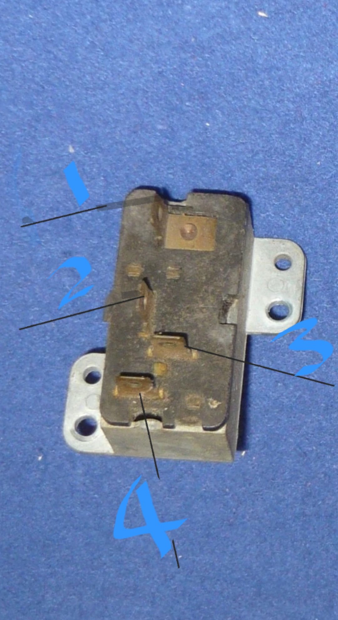
Lost part of my wiring diagram for my headlight switch. Can some one tell me which way to wire this back up. When I replaced the harness me and my stupidity didn't reuse the factory plug for this thing. I'm think there are 2 12V inputs on it I think. I think I recall maybe the upper range of the switch had an input for the headlights and maybe the dimmer. My shop manual is being borrowed by my buddy at the time being or I would dig through that. Attached is a picture of what I'm trying to wire properly.
Screenshot_20260729_142226_eBay.jpg
 
Lost part of my wiring diagram for my headlight switch. Can some one tell me which way to wire this back up. When I replaced the harness me and my stupidity didn't reuse the factory plug for this thing. I'm think there are 2 12V inputs on it I think. I think I recall maybe the upper range of the switch had an input for the headlights and maybe the dimmer. My shop manual is being borrowed by my buddy at the time being or I would dig through that. Attached is a picture of what I'm trying to wire properly.

View attachment 157486

Using the marked numbers in the picture of the switch rear, the connections are as follows

  1. Terminal "B1", Black/White* wire to main power splice
  2. Terminal "R", Black wire to panel dimmer switch and rear body connector
  3. Terminal "B2", Pink wire to fuse box ("Tail Lamps")
  4. Terminal "H", Light Green wire to dimmer switch
The following image shows a diagram of the switch:
Screenshot 2026-07-29 3.13.04 PM.png


The following image shows a picture of the switch with connector and wiring:
Screenshot 2026-07-29 3.29.48 PM.png


Using the marked numbers in the picture of the switch rear, the connections are as follows

  1. Terminal "B1", Black/White* wire to main power splice
  2. Terminal "R", Black wire to panel dimmer switch and rear body connector
  3. Terminal "B2", Pink wire to fuse box ("Tail Lamps")
  4. Terminal "H", Light Green wire to dimmer switch
The following image shows a diagram of the switch:
View attachment 157489


The following image shows a picture of the switch with connector and wiring:
View attachment 157488


Perfect. So there are 2 power wires going to the switch. I'll run a jumper to verify the tail lights just to make sure. Just reverse a voltage tester and that should do it.
 
Perfect. So there are 2 power wires going to the switch. I'll run a jumper to verify the tail lights just to make sure. Just reverse a voltage tester and that should do it.
Two power feeds connect to the switch, but they are fed separately and differently for a reason.
  • Terminal "B1", is fed by the Black/White* wire from the main power splice, which is unfused. When switched on to the headlamp position, the internal contacts connect "B1" to terminal "H", then to the Light Green wire to the dimmer switch, which feeds the headlights. The headlight circuit is protected by the internal, auto-reset, breaker in the headlight switch itself.

  • Terminal "B2", is fed by the Pink wire from the fuse box, and the "Tail Lamps" fuse. When switched on to the headlamp or the parking lights position, the different internal contacts connect "B2" to terminal "R", then to the Black wire to panel dimmer switch, which feeds the dash lights, and to the rear body connector, in the kick panel, which feeds the tail lights, and also the parking lights and side marker lights (Black/Yellow*) which tap from the circuit. The tail light, and related lights, circuit is protected by the "Tail Lamps" fuse.
The two circuits are independent and separate electrically, but controlled mechanically by the same toggle on the dash.

 
Back
Top