• Welcome to For E Bodies Only !

    We are a community of Plymouth Cuda and Dodge Challenger owners. Join now! Its Free!

72 Challenger wiring problems

WhiskeyRebel

Active Member
Joined
Aug 30, 2019
Messages
30
Reaction score
17
Hi all, would appreciate some help sorting some wiring issues. Has anyone ever noticed the diagrams for the 72 and 73 Challenger are slightly different:
http://www.mymopar.com/downloads/1972/72ChallengerB.JPG
http://www.mymopar.com/downloads/1973/73ChallengerA.JPG

Specifically pins 12 and 24 seem to be swapped between the years (horn and low brake warning). The problem I am having is the M&H replacement harnesses are the same for both years and appear to be for the 73. The harness I have is also missing the gray wire from pin 20 that is supposed to go to the neg on the coil.
20190929_201535.jpg

20190929_201522.jpg

20190929_201512.jpg

My symptoms: temp guage does not work, oil light is on, and no horn (tests fine). Ameter appears to work.

This black wire is coming from pin 24:
20190929_194945.jpg

And also has this extra female plug off that wire:
20190929_214008.jpg

According to the 1972 diagram, this should be a red/green wire to the horn. 73 says low brake sw which it appears to be. Just to check I jumped a wire from the horn to that femal plug. No horn still but the brake warning light came on. Seems consistent with the 73. I have no idea where this plugs into? Where is the low brake switch?
 

WhiskeyRebel

Active Member
Joined
Aug 30, 2019
Messages
30
Reaction score
17
Why not try talking to the harness maker, M&H . I am sure they are the right ones to ask about their product.
Reproduction Wiring Harnesses for America's Muscle Cars
Yup, going to call them tomorrow when they open, and will post up what they say. Was wondering if this was a known thing and/or those diagrams are incorrect? Also dont know where that black wire should go assuming the 73 diagram is correct. Does that look like a plug for a low brake switch? This car was half completed when I acquired it so it may be missing parts. And if the 73 diagram is correct and the green/red should go to pin 12, does anyone have any suggestions why my horn does not work?
 

AUSTA

Well-Known Member
Joined
Apr 16, 2015
Messages
937
Reaction score
501
Location
PERTH WA
Hi all, would appreciate some help sorting some wiring issues. Has anyone ever noticed the diagrams for the 72 and 73 Challenger are slightly different:
http://www.mymopar.com/downloads/1972/72ChallengerB.JPG
http://www.mymopar.com/downloads/1973/73ChallengerA.JPG

Specifically pins 12 and 24 seem to be swapped between the years (horn and low brake warning). The problem I am having is the M&H replacement harnesses are the same for both years and appear to be for the 73. The harness I have is also missing the gray wire from pin 20 that is supposed to go to the neg on the coil.
View attachment 63787
View attachment 63788
View attachment 63789
My symptoms: temp guage does not work, oil light is on, and no horn (tests fine). Ameter appears to work.

This black wire is coming from pin 24:
View attachment 63790
And also has this extra female plug off that wire:
View attachment 63791
According to the 1972 diagram, this should be a red/green wire to the horn. 73 says low brake sw which it appears to be. Just to check I jumped a wire from the horn to that femal plug. No horn still but the brake warning light came on. Seems consistent with the 73. I have no idea where this plugs into? Where is the low brake switch?
I think the grey is for the rallye tacho
Also check continuity of each wire with a meter or test light i have had a few M&H looms crimped on the plastic instead of the conductor both main & tail light also a M & H 70 tail light with 1 of the globe sockets with 2 parallel pins instead of offset nearly caused a fire well there was a lot of smoke.
 

WhiskeyRebel

Active Member
Joined
Aug 30, 2019
Messages
30
Reaction score
17
Called M&H tech help and they confirmed the 72 diagram on the mymopar site and in the manual is incorrect. 72 and 73 should be identical according to the Mopar schematics he was comparing to. The 72 diagram may be a holdover from 71 as it matches that diagram. He did also confirm the missing gray goes to the tach. Ok, now that I know I need to use the 73 diagram, I have some more investigation to do.

Regarding the brake pressure switch; is this on the distribution block? My car has an aftermarket with some plugged ports. Anyone know where I can get the switch? Maybe this is a salvage yard item? I cant find a single pin one that I think goes here, all the aftermarket ones have two pins. Anyone have a picture of what theirs looks like?

Thanks for all the help.
 

WhiskeyRebel

Active Member
Joined
Aug 30, 2019
Messages
30
Reaction score
17
Ok so here is where I am at with sorting the horn not working.
I have tested the horns by applying power directly and they work.
I have tested the horn button in the steering column with a test light, applied a positive source to the pointy end and clipped to the black wire on the tab in the wheel. It works when the button is depressed completing the ground.
Ive tested the horn by applying postive to the green/red in the pic below of the back of the fuse box. This is where the relay plugs in. Horn works from there.
20191003_142824.jpg

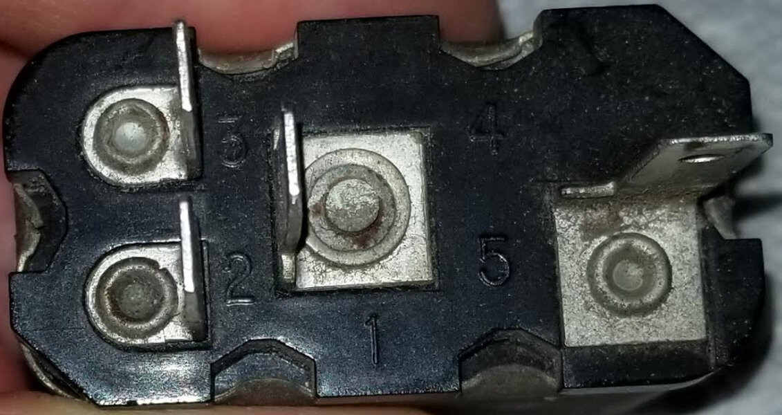
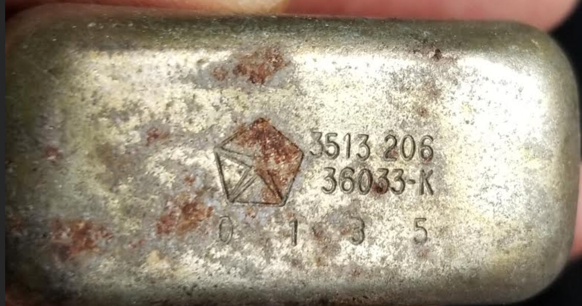
The violet is the positive feed, green/red goes to horn, the black on the left is the key in buzzer, and the black/white is from the horn switch. Here is the relay:
20191003_151418.jpg

To test this I applied a positive feed to #1. Applying ground to #5 activates the buzzer. Applying ground to #2 should give me 12v to #3 but it does not. Do you all agree with this and think my relay is bad? Can the buzzer still work but the horn side of the relay fail?
 

WhiskeyRebel

Active Member
Joined
Aug 30, 2019
Messages
30
Reaction score
17
One thing still not making sense is why is that ground wire from the horn black/white? Shouldnt this be solid black like the wire in the horn? I also have not been able to get a test light to work at that black white wire. I put my light on a positive source and the neg on that black/white wire. Pressing the horn should complete that curcuit, no?
 
Last edited:

RayL

Well-Known Member
Joined
May 15, 2021
Messages
47
Reaction score
13
Location
NJ
Sorry to resurrect an old thread, but this one is exactly my situation. I've done the same horn relay tests as WhiskeyRebel with the same result. Two questions: 1) is the test correct? 2) Where can I get a replacement 4 prong relay? I've been checking all the sources I know of and can only find the '70 three prong relay.
 

Attachments

  • 2021-05-24_203534.jpg
    2021-05-24_203534.jpg
    150.4 KB · Views: 164
  • 2021-05-24_202912.jpg
    2021-05-24_202912.jpg
    206.9 KB · Views: 161

72RoadRunnerGTX

Well-Known Member
Joined
Jan 8, 2013
Messages
193
Reaction score
114
Location
Shoreline. Washington
Do a search on Ebay for "Mopar 3579204", a couple of NOS relays and a couple repo sellers presently.
Yes, the test outlined above is correct, with power on terminal #1, applying a ground to #2 should produce a click and voltage on #3. If not, find another relay.
 
Last edited:

RayL

Well-Known Member
Joined
May 15, 2021
Messages
47
Reaction score
13
Location
NJ
Thanks. Good to know the test procedure is valid. I'll be ordering one soon.
 

RayL

Well-Known Member
Joined
May 15, 2021
Messages
47
Reaction score
13
Location
NJ
Following up on this thread. I ordered a Mopar 3579204 in eBay. The spacing of the connectors didn't match the OEM part on the one I received. After some searching I discovered the Prestolite 9-9C SRP-1164 was the identical part and much cheaper. Ordered one on eBay and my horn is back in action. Thanks for all the support!
 
Back
Top